


Download the PDF Here
Contents
Installation and Configuration of Rooftop Solar Systems
- Drawing Package
- Mounting System Installation
- Inverter Installation and Configuration
- Panel Installation
- Wiring and Installation
- Testing and Commissioning
- Common Mistakes
Drawing Packages for Installers
These drawings (site layout, SLD) will be provided to you prior to installation. You will need to confirm that you have all of the equipment listed on the drawings prior to leaving the shop.
Installing to the system exactly as shown on the drawings is required to pass inspections.
Single Line Diagram

Site Layout

Site Layout with Panel Quantity

Racking System Components and Installation
The following slides will provide you with the basic components of the roof-mounted racking system and a general overview of how they are assembled
Having a proper racking layout is integral to ensuring that the system fits properly on the roof.

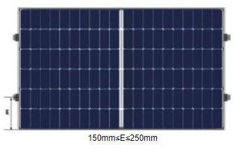
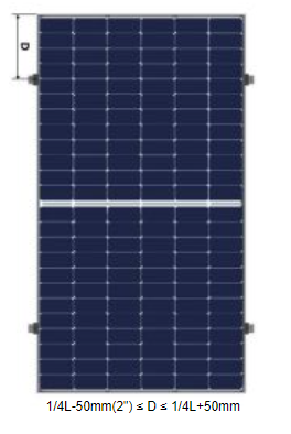
L-Foot and Flashing

Feet and Flashing

- Distance between L-Feet should be
no greater than 4ft (48in). Stagger each row of
L-brackets to distribute the load evenly
between all trusses. - Distance from last L-Foot to rail end
should be no more than 1 ft (12in). - If panels are overhanging the roof (this
should be avoided), spacing between
L-brackets should be 2ft (24in) on the rail closest to the edge. - Normal installation will have the L-bracket sitting just 1 rib from flush to rail, depending on how level the roof sheeting is, you may need to adjust their height.
- When adding a joiner to rails, you must leave a gap ¼” – ⅜” for thermal expansion. A bonding strap is also required between expansion joints.
- The talon flashings are required to sit under 1.5 – 2 shingles so that only the raised part that holds the L-bracket is exposed. This may mean moving your row up or down a couple inches so your talon plate does not cross over 2 shingles.
Talon and Fast Rack Installation Videos
Fast Rack Talon Solar Installation Overview
Fast Rack and Low Profile Demo
Bonding


All rails, conduits, flex, junction boxes and other metal parts on the rooftop must be bonded with the No.6 bare bond cable.

All Rails must be connected by a continuous bond. This includes when running through liquid tight or zip
tied to the teck to join sections of the array when it is broken up.
When arrays are broken up, Metallic Flex (liquid-tight) must be used to shield the RPVU from mechanical
damage.
One 1 end, a connector and ground bushing are required and just a bushing or insulated sleeve on the
other end.
Once all cables have been run through, both ends of the liquid tight should be duct-sealed.


Micro Inverters

2 Panel Inverters

4 Panel Inverters
Hoymiles Micro-Inverter Installation video.
Inverter Mapping
Inverter mapping is important for monitoring the clients system after install completion. This is done as the inverters are installed, and the racking should be mounted at this point.


Array Wiring Methods
MC4 Connectors

RPVU Cables

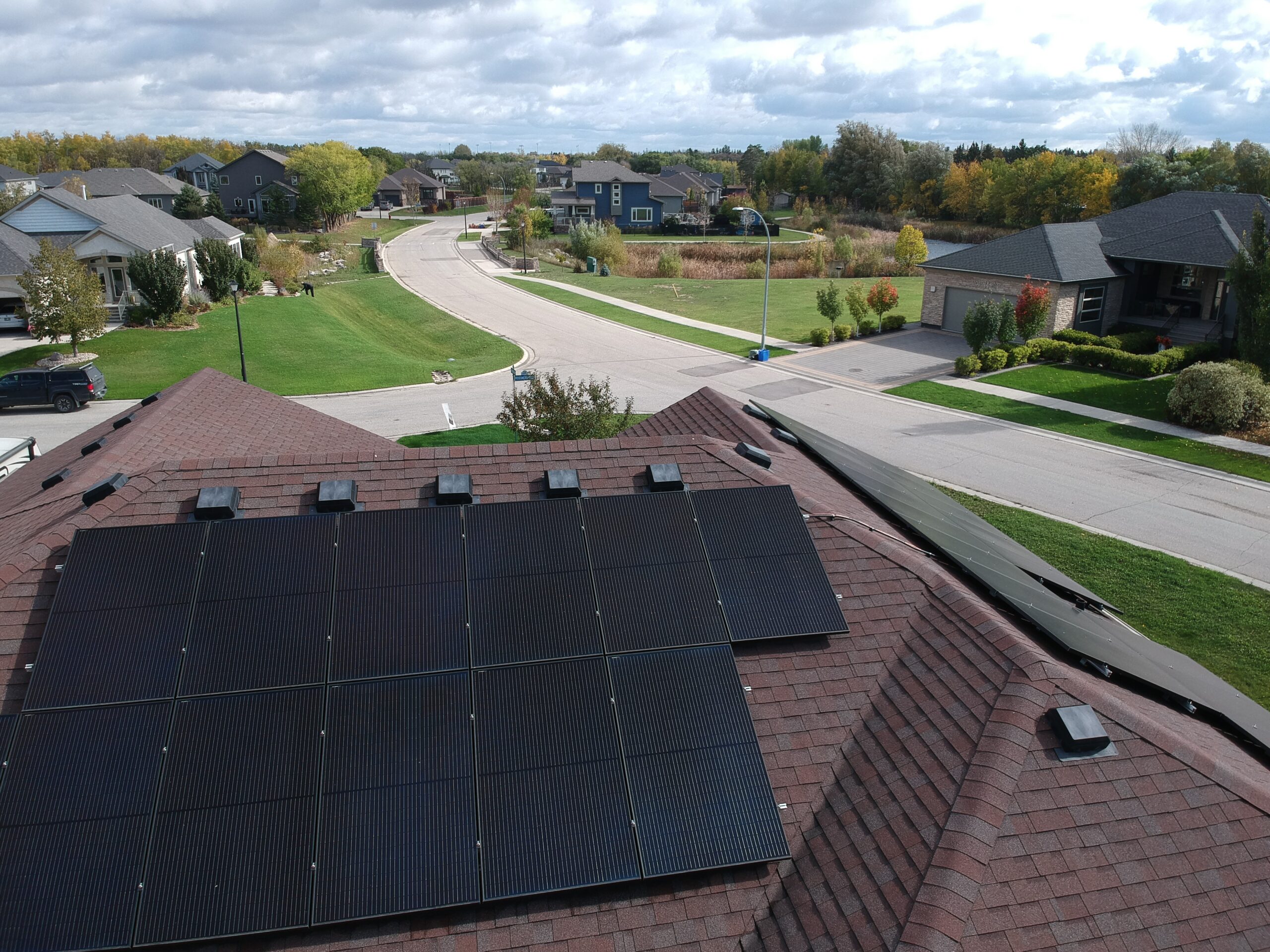
Module Orientation and Mounting
Landscape
VS
Portrait
Lamacoid Labels


Lamacoid Labels & Locations
Panel

Multiple power supplies
Electric shock hazard
AC numerical values (whole system)
Single line Diagram
Photovoltaic system equipped with rapid shutdown
Inverter output location (located as close to the solar breaker as possible.
*The solar breaker must be positioned at the opposite (load) end from the input feeder location.
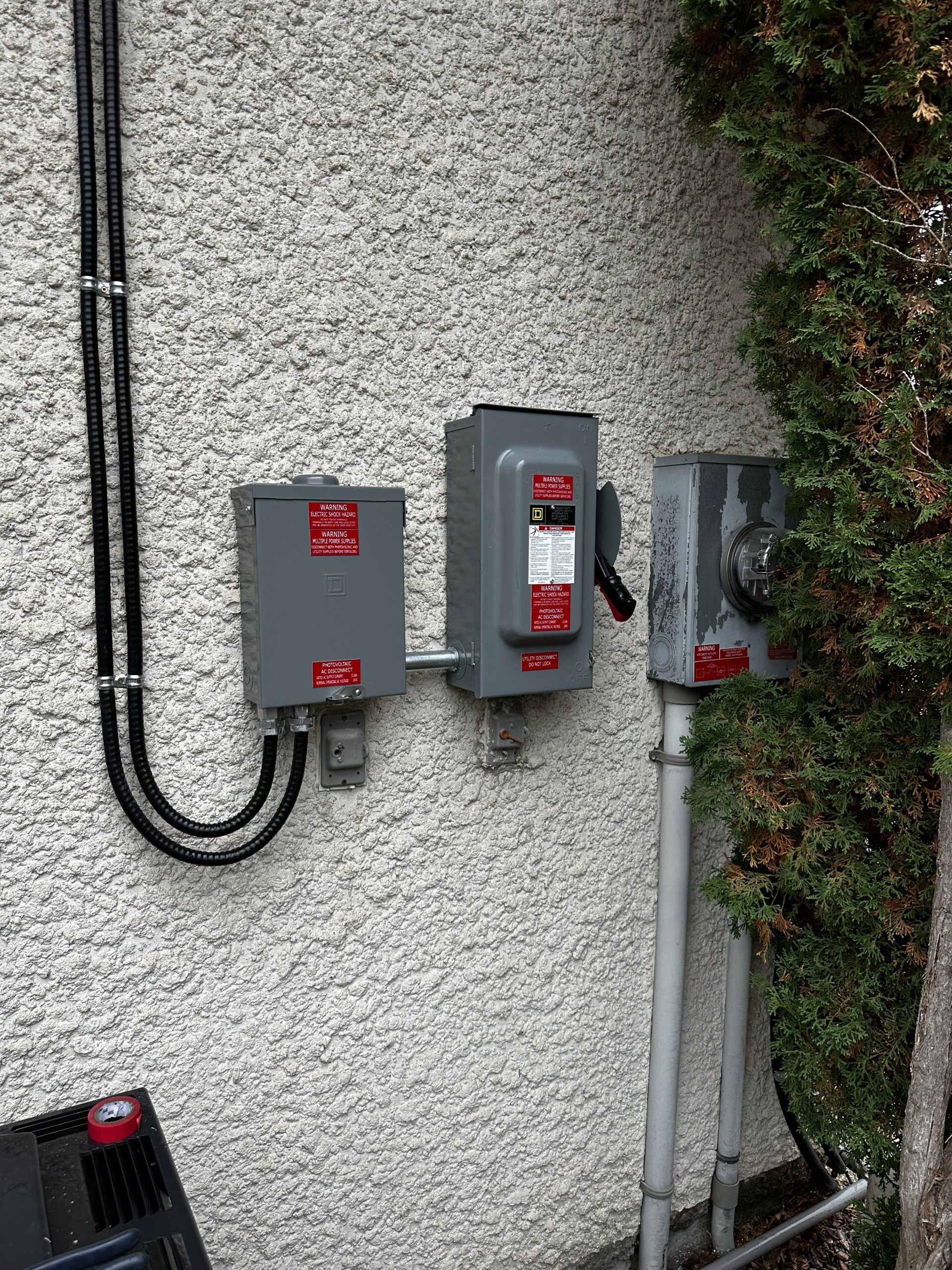
Meter & Utility Disconnect

Interconnected Photovoltaic Source
Single Line Diagram
Photovoltaic system equipped with rapid shutdown
Note: In AC
disconnects the
feed from the grid is wired to the “line”
side, inverter feed is wired to the “load”
side.
AC Combiner Panel


Multiple power supplies
Electric shock hazard
AC numerical values (whole system)
AC numerical values (Individual strings/breakers)
Other Lamacoid Locations

All junction boxes including on the roof, in the basement, beside the panel, that are part of the solar circuit must have a “Multiple Power Supplies” label put on.
Rooftop Junction Boxes
Do’s
Here’s an example of a proper install of the junction box. One important thing to note is that, you always want to mount the junction box to the rail whenever possible.
Don’ts

The junction box you see above was installed incorrectly. Junction boxes should never be installed directly into the roof without flashing. Flashing is important as it prevents water damage to the customers home.
Commissioning the System

Once the system is installed you will need to install the monitoring system inside the home and connect it to the homeowners network. The monitoring systems differ depending on the inverter brand.
Apsystems ECU Setup
There are about 10 steps to follow when setting up the ECU for the customer.
- The first step is to download the EMA Manager App. 2.
- Next step is to turn off your cell phone data as this interferes with the setup.
- Following this you are going to press the white button on the side of the unit marked AP
- At this point your phone should pick up a wifi signal thats named ECU-R followed by a bunch of numbers ex. ECU-R 216200004314.
- The password for wifi should be 88888888.
6. Now you can sign in, go to your EMA monitoring app and click local access button highlighted in blue as shown in the figure.

7. On your next screen here you should see an option at the bottom that says workspace, click that and it should take you to a new screen

8. Click on ECU network settings highlighted below and it should bring you to the next screen.

9. Click on the WLAN settings and click the switch to on.

10. The last step is to connect your network. Find your network below and put in your current wifi password and it should be all set!

Hoymiles DTU Setup

The Hoymiles DTU takes 6 steps to setup.
- Download the S-miles Installer
- Open the app and log in.
- Select the bottom middle tab and open Network Config, this will prompt you to locate the DTU through wifi.
- Connect DTU through wifi or LAN.
- You may need to add the network name and password both manually.
- And lastly, the DTU can either be connected directly to the router or connected through wifi.
Inspection Photos


Inspection Photos


Hands on Skills Required
- Installing anchor points & roof patching
- Measuring a roof for panel and racking layout
- Crimping RPVU Cables


Common Mistakes
- Installation differs from plans (different equipment, locations, wire or breaker sizes
- Missing Lamacoids
- Missing note
- Roof and junction box photos
- Wires not clipped up off roof properly
- Ground bushings or rail bonding not installed or documented
- Mixing up line and load in disconnects